How to Build a 12V PWM Motor Speed Controller (Step-by-Step)
Introduction
Want to control the speed of a 12V DC motor efficiently? A Pulse Width Modulation (PWM) motor speed controller is the best solution! Unlike traditional methods that reduce voltage (wasting power as heat), PWM optimizes energy usage while providing smooth speed control.
This guide will walk you through the step-by-step process of building a 12V PWM motor controller using affordable and easily available components. Whether you're into robotics, DIY projects, or fan speed control, this project is a great addition to your electronics skills.
Required Components
Here’s what you’ll need to build the controller:
Main Components:
- 555 Timer IC – Generates the PWM signal.
- IRFZ44N N-Channel MOSFET – Acts as the motor driver.
- 10kΩ Potentiometer – Adjusts the motor speed.
- 1kΩ Resistor (x1)
- 100Ω Resistor (x1)
- 0.1µF Ceramic Capacitor (x1)
- 1N4007 Diode – Protects against back EMF.
Additional Materials:
- Breadboard or PCB – For circuit assembly.
- 12V DC Motor
- 12V Power Supply (Battery or Adapter)
- Heat Sink To prevent the MOSFET from overheating.
- Jumper Wires – For easy connections.
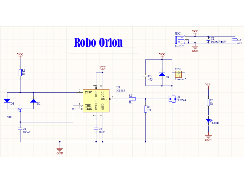
Circuit Diagram
Below is the PWM Motor Controller Circuit Diagram based on a 555 timer and MOSFET.
Step-by-Step Assembly Guide
Step 1: Understanding How the Circuit Works
The 555 timer IC runs in astable mode, generating a square wave signal. The duty cycle (width of the pulses) controls the motor speed and is adjusted using a potentiometer. The MOSFET amplifies this signal to power the motor efficiently.
Step 2: Building the Circuit on a Breadboard
- Insert the 555 Timer IC into the breadboard.
- Connect the power supply:
- Pin 8 (VCC) → 12V Positive
- Pin 1 (GND) → Ground
- Add timing components:
- 0.1µF capacitor between pin 5 (CONT) and GND.
- 1kΩ resistor between pin 7 (DIS) and pin 6 (THR).
- 10kΩ potentiometer between pin 7 and VCC.
- Wire the MOSFET (IRFZ44N):
- Gate (G) → 555 timer’s pin 3 (Output) via a 100Ω resistor.
- Drain (D) → Motor’s positive terminal.
- Source (S) → Ground.
- Add the diode (1N4007) across the motor terminals (cathode to motor’s +ve).
Step 3: Testing the Circuit
- Power the circuit and turn the potentiometer to adjust the speed.
- Check the PWM output on pin 3 of the 555 timer using a multimeter (expect 0-12V fluctuations).
- If the motor doesn't spin, check the MOSFET wiring and component connections.
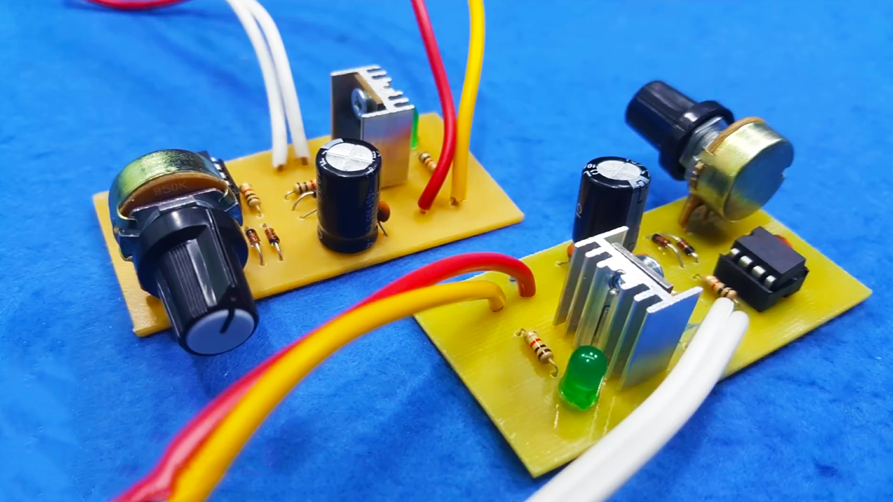
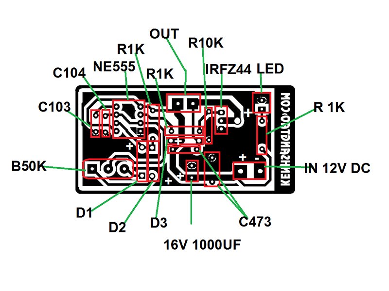
Step 4: Transferring to a PCB (Optional for Permanent Use)
- Solder the components onto a PCB following the same layout as on the breadboard.
- Attach a heat sink to the MOSFET to prevent overheating.
Final Assembly & Enclosure (Optional)
- Mount the potentiometer on an enclosure for easy speed adjustments.
- Secure wiring using hot glue or zip ties.
- Optionally, add an LED indicator to show power status.
Safety Tips
- Double-check wiring before applying power.
- Use a fuse (1-2A) in series with the power supply to protect the circuit.
- Disconnect power before making modifications.
Troubleshooting Guide
| Issue | Possible Cause | Solution |
|---|---|---|
| Motor doesn’t spin | Incorrect MOSFET wiring or damaged 555 IC | Check wiring, replace IC/MOSFET |
| No PWM output | Wrong potentiometer value | Use a 10kΩ potentiometer |
| MOSFET overheating | No heat sink or incorrect wiring | Add a heat sink, verify connections |
Conclusion
Congratulations! You have successfully built a 12V PWM Motor Speed Controller. This project is a cost-effective way to control DC motor speed with efficiency and precision.
You can experiment with:
- Different potentiometer values to modify the speed range.
- Adding an LED indicator to visualize the PWM signal.
- Using a higher-power MOSFET for larger motors.
If you found this guide helpful, feel free to share your feedback in the comments. Happy building and keep innovating!
Related Link
Diy High Voltage Generator
Gallery

Robo Orion
We are always active for you. Whenever you needs help, contact with us.