Introduction
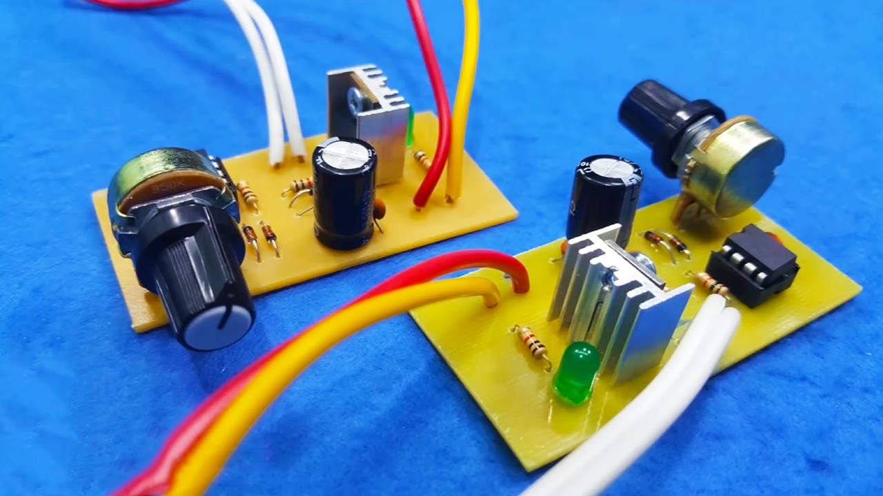
PWM stands for "Pulse Width Modulation" – A PWM DC motor speed control circuit is basically an electronic device that controls how fast a motor runs by rapidly switching the power on and off.
Wants to control the speed of a 12V DC motor efficiently? A pulse width modulation motor controller is the best solution! Unlike traditional methods that reduce voltage (wasting power as heat), PWM optimizes energy usage while providing smooth speed control.
In this tutorial, I am going to show you how to make a DIY PWM motor controller circuit which can even control a 12V high power 775 motor speed easily.

Circuit Diagram
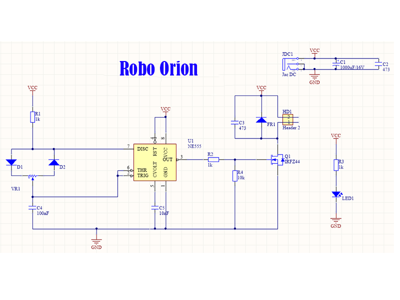
Below is the 12V PWM motor speed controller circuit diagram schematic.

Required Components
- 555 Timer IC - Generates the PWM signal (555 timer PWM circuit).
- IRFZ44N N-Channel MOSFET - Acts as the MOSFET motor driver circuit.
- 10kΩ Potentiometer - Adjusts the motor speed (motor control with potentiometer).
- 1kΩ Resistor (x1)
- 100Ω Resistor (x1)
- 0.1µF Ceramic Capacitor (x1)
- 1N4007 Diode - Protects against back EMF (protecting DC motor from back EMF).
- Push Buttons
Additional Materials
- Breadboard or PCB - For circuit assembly (breadboard DC motor speed controller setup).
- 12V DC Motor
- 12V Power Supply (Battery or Adapter)
- Heat Sink - To prevent the MOSFET from overheating (heat sink for MOSFET in motor controller).
- Jumper Wires - For easy connections.
Conclusion
This homemade DC motor speed controller project is a cost-effective way to regulate DC motor speed with efficiency and precision. Whether you are building DIY electronics projects for beginners or experimenting with robotics, this 12V PWM motor controller is a practical choice.
If you found this guide helpful, feel free to share your feedback. Happy building and keep innovating!
Published by: Robo Orion
Date: September 5, 2025
Category:Tutorials, Electronics